Unity想要实现圆形图片,需要使用Mask,不是基于Mesh实现的,这里我们自己写一个基于Mesh的圆形图片组件。
新建Scene,命名为“CircleImage”,在Scripts文件夹内新建“CircleImage”文件夹。
Mask圆形遮罩
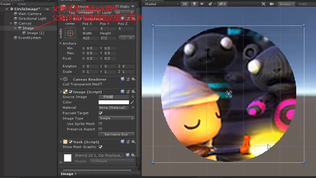
缺点:锯齿感强,增加DrawCall
CircleImage
在“CircleImage”文件夹内新建同名脚本文件
1
2
3
4
5
6
7
8
9
10
11
12
13
14
15
16
17
18
19
20
21
22
23
24
25
26
27
28
29
30
31
32
33
34
35
36
37
38
39
40
41
42
43
44
45
46
47
48
49
50
51
52
53
54
55
56
57
| using UnityEngine;
using UnityEngine.Sprites;
using UnityEngine.UI;
public class CircleImage : Image
{
[SerializeField] private int segments = 100;
[SerializeField] private float showPercent = 1;
protected override void OnPopulateMesh(VertexHelper vh)
{
vh.Clear();
float width = rectTransform.rect.width;
float height = rectTransform.rect.height;
int realSegment = (int)(segments * showPercent);
Vector4 uv = overrideSprite != null ? DataUtility.GetOuterUV(overrideSprite) : Vector4.zero;
float uvWidth = uv.z - uv.x;
float uvHeight = uv.w - uv.y;
Vector2 uvCenter = new Vector2(uvWidth * 0.5f, uvHeight * 0.5f);
Vector2 convertRatio = new Vector2(uvWidth/width, uvHeight/height);
float radian = (2 * Mathf.PI) / segments;
float radius = width * 0.5f;
UIVertex origin = new UIVertex();
origin.color = color;
origin.position = Vector3.zero;
origin.uv0 = new Vector2(origin.position.x * convertRatio.x + uvCenter.x,origin.position.y * convertRatio.y + uvCenter.y);
vh.AddVert(origin);
int vertexCount = realSegment + 1;
float curRadian = 0;
for (int i = 0; i < vertexCount; i++)
{
float x = Mathf.Cos(curRadian) * radius;
float y = Mathf.Sin(curRadian) * radius;
curRadian += radian;
UIVertex vertexTemp = new UIVertex();
vertexTemp.color = color;
vertexTemp.position = new Vector2(x, y);
vertexTemp.uv0 = new Vector2(vertexTemp.position.x * convertRatio.x + uvCenter.x, vertexTemp.position.y * convertRatio.y + uvCenter.y);
vh.AddVert(vertexTemp);
}
int id = 1;
for (int i = 0;i < realSegment;i++)
{
vh.AddTriangle(id, 0, id + 1);
id++;
}
}
}
|
OnPopulateMesh,Image组件的绘制方法。
VertexHelper,一个绘制数据载体类,提供了一系列方法,GPU通过这个类来获取顶点数据、片元数据等。
Class VertexHelper | Unity UI | 1.0.0 (unity3d.com)
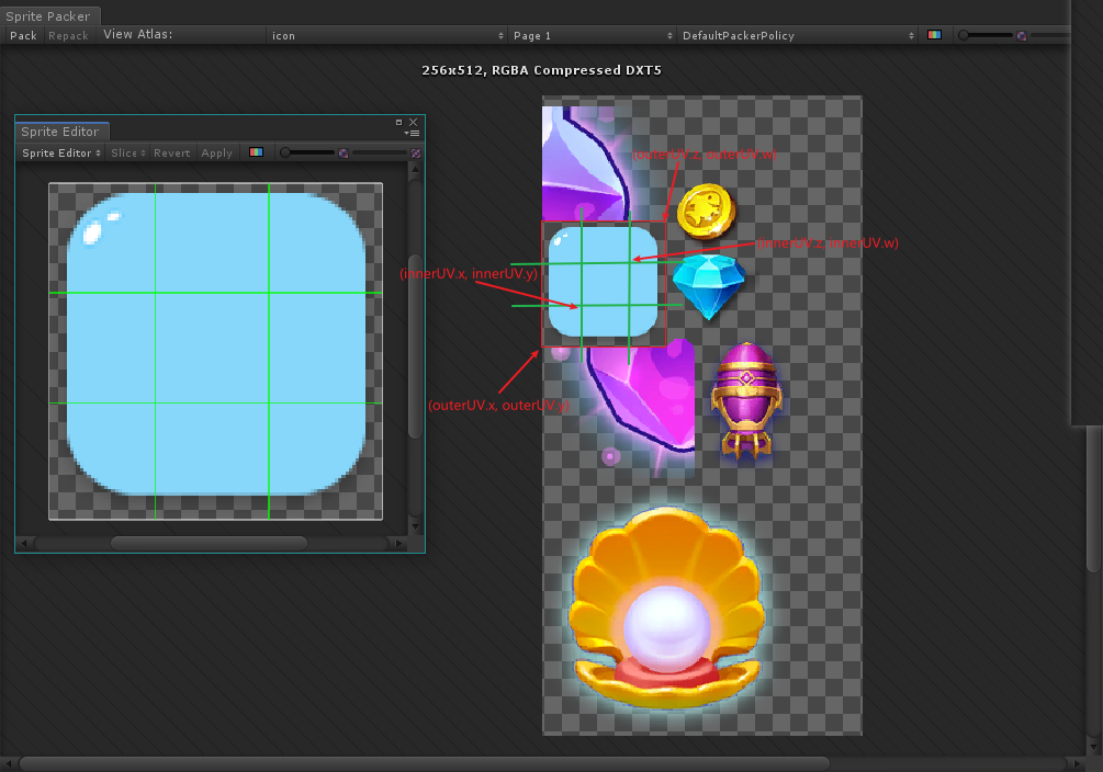
DataUtility,一个获取Sprite的UV和Size等数据的工具类。这里的GetOuterUV方法获取的是图像的完整UV,如果一个Sprite是九宫格格式,InnerUV指的就是九宫格内部的UV。
注意,Sprite的OuterUV是一个Vector4,而一般的UV是Vector2,因为OuterUV和InnerUV是对应的,必须要Vector4才能计算出外部和内部的区别。Vector4(x,y,z,w)
overrideSprite是Image组件提供的变量,它指的就是“覆盖在上层”的Sprite,因为有些时候Image的sprite变量为空,而overrideSprite一般并不会为空
原理图
绘制原理

在代码中,顶点的ID是按照添加到VertexHelper.AddVertex的顶点的顺序决定的,第一个ID编号是0
只有顺时针绘制,GPU才能视为正面。默认背面是剔除的。
坐标原理
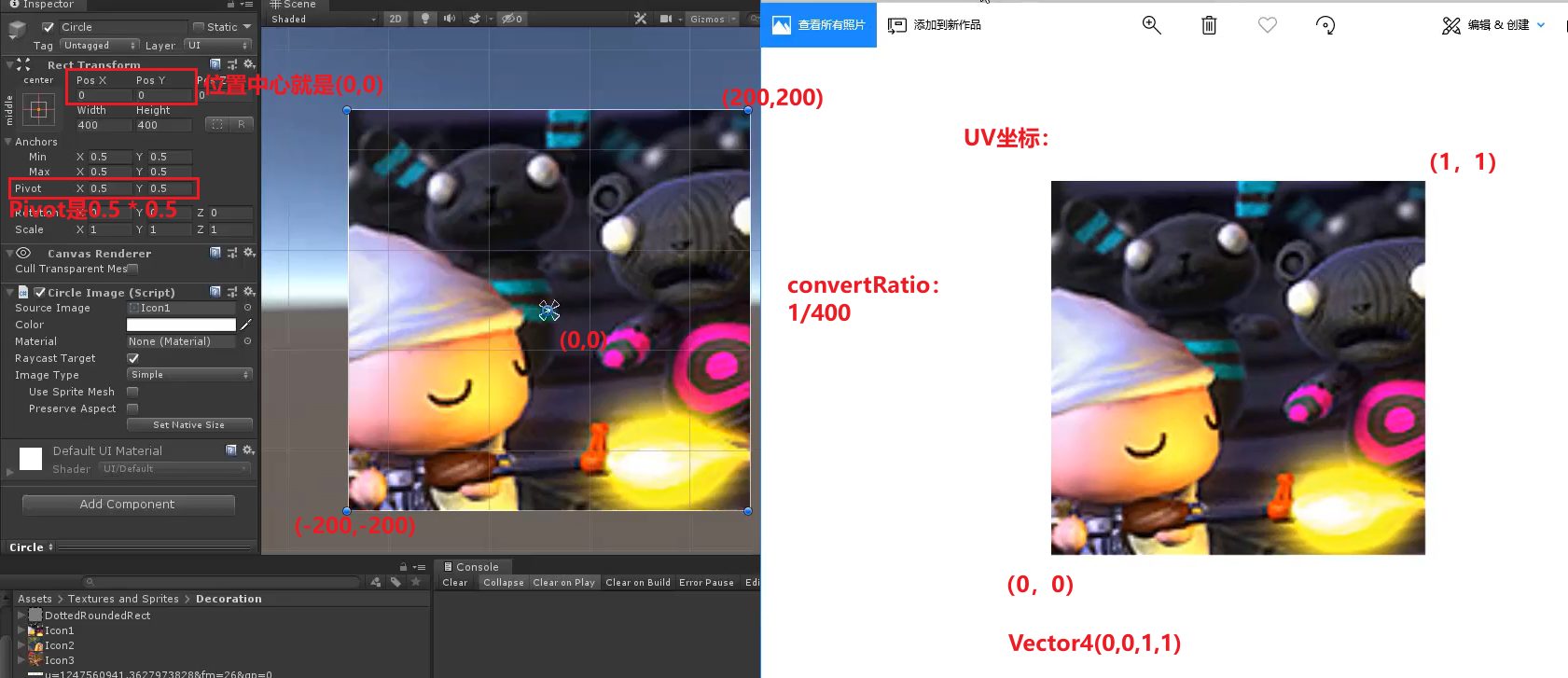
想要把uv正确设置出来,需要在乘转换系数(convertRatio)的同时再添加uv的偏移量。
顶点在Rect组件中的位置 * convertRatio + uvCenter
CircleImage编辑器拓展
在Scripts——CircleImage文件夹内新建Editor文件夹,在其中新建CircleImageEditor脚本
1
2
3
4
5
6
7
8
9
10
11
12
13
14
15
16
17
18
19
20
21
22
23
24
25
26
27
28
| using UnityEngine;
using UnityEditor;
[CustomEditor(typeof(CircleImage))]
[CanEditMultipleObjects]
public class CircleImageEditor : UnityEditor.UI.ImageEditor
{
SerializedProperty mSegments;
SerializedProperty mFillPercent;
protected override void OnEnable()
{
base.OnEnable();
mSegments = serializedObject.FindProperty("segments");
mFillPercent = serializedObject.FindProperty("showPercent");
}
public override void OnInspectorGUI()
{
base.OnInspectorGUI();
serializedObject.Update();
EditorGUILayout.PropertyField(mSegments);
EditorGUILayout.Slider(mFillPercent,0,1,new GUIContent("showPercent"));
serializedObject.ApplyModifiedProperties();
if(GUI.changed)
{
EditorUtility.SetDirty(target);
}
}
}
|
技能CD效果
我们修改一下CircleImage的代码,就能实现技能CD的效果。
1
2
3
4
5
6
7
8
9
10
11
12
13
14
15
16
17
18
19
20
21
22
23
24
25
26
27
28
29
30
31
32
33
34
35
36
37
38
39
40
41
42
43
44
45
46
47
48
49
50
51
52
53
54
55
56
57
58
59
60
61
62
63
64
65
66
67
68
69
70
71
72
73
74
75
76
| using UnityEngine;
using UnityEngine.Sprites;
using UnityEngine.UI;
public class CircleImage : Image
{
[SerializeField] private int segments = 100;
[SerializeField] private float showPercent = 1;
protected override void OnPopulateMesh(VertexHelper vh)
{
vh.Clear();
float width = rectTransform.rect.width;
float height = rectTransform.rect.height;
int realSegment = (int)(segments * showPercent);
Vector4 uv = overrideSprite != null ? DataUtility.GetOuterUV(overrideSprite) : Vector4.zero;
float uvWidth = uv.z - uv.x;
float uvHeight = uv.w - uv.y;
Vector2 uvCenter = new Vector2(uvWidth * 0.5f, uvHeight * 0.5f);
Vector2 convertRatio = new Vector2(uvWidth/width, uvHeight/height);
float radian = (2 * Mathf.PI) / segments;
float radius = width * 0.5f;
UIVertex origin = new UIVertex();
byte temp = System.Convert.ToByte(255 * showPercent);
origin.color = new Color32(temp, temp, temp, 255);
Vector2 originPos = new Vector2((0.5f - rectTransform.pivot.x) * width, (0.5f - rectTransform.pivot.y) * height);
Vector2 vertPos = Vector2.zero;
origin.position = originPos;
origin.uv0 = new Vector2(vertPos.x * convertRatio.x + uvCenter.x,vertPos.y * convertRatio.y + uvCenter.y);
vh.AddVert(origin);
int vertexCount = realSegment + 1;
float curRadian = 0;
Vector2 posTemp;
for (int i = 0; i < segments + 1; i++)
{
float x = Mathf.Cos(curRadian) * radius;
float y = Mathf.Sin(curRadian) * radius;
curRadian += radian;
UIVertex vertexTemp = new UIVertex();
if (i < vertexCount - 1)
{
vertexTemp.color = color;
}
else if(showPercent >= 1)
{
vertexTemp.color = color;
}
else
{
vertexTemp.color = new Color32(60, 60, 60, 255);
}
posTemp = new Vector2(x, y);
vertexTemp.position = posTemp + originPos;
vertexTemp.uv0 = new Vector2(posTemp.x * convertRatio.x + uvCenter.x, posTemp.y * convertRatio.y + uvCenter.y);
vh.AddVert(vertexTemp);
}
int id = 1;
for (int i = 0;i < segments;i++)
{
vh.AddTriangle(id, 0, id + 1);
id++;
}
}
}
|
代码中加注释的地方就是重点修改的地方,注意阴影绘制的方式和pivot中心点的换算。